Standpipe BasicsComment on this page
Original article → Standpipe System Operations: Engine Company Basics
By Author(s): Andrew A. Fredericks
Published January 2, 1996 | From Volume 149, Issue 2 of Fire Engineering
When fires occur in buildings equipped with standpipe systems, engine companies are responsible for completing three critical tasks:
- Supplying or augmenting the standpipe system to ensure an adequate volume of water at proper pressure;
- Transporting hose, nozzles, fittings, and other tools to the hose outlet valve selected for use; and
- Stretching and advancing a hoseline to control and extinguish the fire.
Before examining each of these tasks and some of the many difficulties encountered when operating with standpipe systems, let`s briefly review the various types of standpipe systems and where they might be found. (A bibliography is provided at the end of this article for reference and further study.)
Types of Standpipe Systems
Standpipe systems are categorized according to the size (diameter) of the hose outlets and as being either “wet” or “dry.” NFPA 14, Standard for the Installation of Standpipe and Hose Systems (1993 edition), establishes three classes of standpipe systems:
- Class I – 2 1/2-inch outlets for firefighter use,
- Class II – 1 1/2-inch outlets with 1 1/2-inch hose for occupant use, and
- Class III – 2 1/2-inch outlets and 1 1/2-inch outlets or 2 1/2-inch outlets reduced to 1 1/2-inch with a removable fitting for occupant and firefighter use. Usually 1 1/2-inch “occupant-use” hose is provided.
Some Class III systems may not contain any occupant-use hose (also called “house line”), especially in buildings protected by automatic sprinklers. In older industrial and manufacturing buildings (and some residential buildings), 2 1/2-inch occupant-use hose may be encountered. Engine companies should never attempt to use the unlined, linen hose provided with standpipe systems. It often is old and improperly maintained and may fail under fire department operating pressures. An exception to this rule applies to a ladder or rescue company operating remotely from an engine company while performing searches. Stretching and operating occupant-use hose would be justified in an attempt to save civilian and firefighter lives.
Wet standpipe systems contain water in the riser at all times. The water is supplied by municipal main, gravity tank, pressure tank, or a combination of these sources. In many cases, manual or automatic fire pumps are used in conjunction with municipal water supplies to boost pressures on the upper floors of tall buildings.
Standpipe systems may also be “dry.” Some dry standpipes operate on the same principle as automatic dry sprinkler systems. Just as water is admitted to a dry sprinkler riser automatically when pressurized air is exhausted through an open sprinkler head, water enters the dry standpipe riser once the air is released through an open hose outlet valve. Other types of dry standpipes use a deluge-type of valve. Supply sources for automatic dry standpipe systems are the same as those for wet systems. Many dry systems, however, have no automatic source of supply and depend solely on fire department pumpers to provide the system demand.
A combination system or combination sprinkler/standpipe consists of sprinkler heads and standpipe hose outlets attached to a common riser.
Locations of Standpipe Systems
Requirements for installing standpipe systems are predicated on several factors, the primary of which are the height and area of the building or structure. Many building codes require that standpipes be installed in buildings that exceed three stories in height or pose special hazards associated with their large floor areas or occupancy type. In many older cities, especially in the Northeast and upper Midwest, it is not uncommon to find multiple dwellings up to seven stories in height without standpipe systems. In my area of the Bronx (New York), manual hose stretches of 10, 11, and 12 lengths (500 to 600 feet) sometimes are required for top-floor fires in these buildings. A recent Bronx fire required some 17 lengths (850 feet) of hose to reach the burning apartment.
Other factors also influence the need for standpipe systems. In locations that do not afford access to fire apparatus, such as parking garages, standpipes usually are required. Where excessive distance precludes laying supply hose or manually stretching handlines, such as on bridges or in tunnels, standpipe systems may be required as well. A list of locations often equipped with standpipe systems follows:
- high-rise residential and office buildings;
- large-area buildings such as hospitals, terminals, warehouses, manufacturing facilities, and industrial buildings;
- enclosed shopping malls;
- theaters, stadiums, and arenas;
- above and below-grade parking garages;
- bridges and tunnels;
- limited-access highways; and
- piers and wharves.
Engine companies must conduct preincident planning activities to identify the locations of standpipe systems within their response areas and any associated problems or special characteristics.
The remainder of this article is directed at standpipe operations in high-rise residential and office buildings, since they can be found in almost any community and fires in these buildings present many complex challenges.
Supplying Standpipe Systems
The first critical task facing engine companies arriving at a fire in a standpipe-equipped building is to establish a water supply by pumping into the siamese connections. Hose used to supply standpipe systems should be the largest available and at least three inches in diameter. Some jurisdictions require that building owners provide third-turn or quarter-turn couplings at siamese connections to accommodate four- and five-inch hose. In the case of wet standpipes, fire department pumpers must augment the system to ensure flow needs are met at adequate pressures. In the case of dry standpipe systems, fire department pumpers provide the only water supply available for firefighting.
It is important to provide an independent and a redundant water supply by using a separate pumper for each siamese connection. This ensures that firefighters advancing hoselines will have an uninterrupted supply of water should a pumper suffer a mechanical failure, the siamese connections supply only dedicated risers, or a zone-control valve be shut without firefighters` knowledge. Each engine company assigned on the first alarm should take a position at a nearby hydrant and stretch a supply line to the appropriate siamese connection. The larger the building, the more likely a multiple siamese connection will be present, often on different street fronts.
Common Siamese Connection Problems
Should only a single siamese connection be available or the siamese connection be unusable due to vandalism, the standpipe system can be supplied through a first- or second-floor hose outlet. Supplying a standpipe system through a lower-floor outlet requires that the appropriate fittings and adapters be brought into the building and that any pressure-regulating devices installed at the hose outlet be removed or adjusted to the fully open position so as not to impede the water supply. Note that some pressure-regulating devices (PRDs) cannot be “back-fed” through the discharge side of the hose valve. A more complete discussion of pressure-regulating devices is included below.
Problems caused by vandalized and inadequately maintained siamese connections often will be encountered. Some of these problems may include missing caps, stuck caps, damaged threads, female swivels that do not spin freely, out-of-round female swivels, missing female swivels, garbage- and debris-clogged connections, and broken or jammed-open clapper valves.
Stuck caps and frozen female swivels. It may be possible to loosen trapped dirt and paint by tapping the cap or swivel with a spanner wrench. Large spanner wrenches or a 36-inch pipe wrench may also be needed to free a cap or swivel. If a swivel cannot be loosened, attach a double-male fitting followed by a double-female, thus improvising a swivel and allowing the supply hose to be attached. In areas of high vandalism, “break-away” vandalproof caps may be installed. If they are plastic, it sometimes is possible to strike the cap in the middle, breaking it in two and permitting easy removal. Metal caps usually are best removed by prying one of the screw eyes off its pin lug with the prying end of a spanner wrench. Plastic caps also can be removed in this fashion.
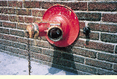
Missing caps. They should not interfere with supply operations unless garbage has been placed in the siamese connection that must be removed or a clapper valve is jammed open, thus allowing water to flow out the uncapped side. Note: Be careful when removing garbage and debris stuffed inside siamese connections. Never stick your fingers or any part of your hand inside a siamese connection to clear it. Junkies have been known to store or discard hypodermic needles in them. If debris or garbage must be removed, a pipe, hydrant, or spanner wrench handle makes an excellent probe. It is a good idea for pump operators or engine company chauffeurs to carry a flashlight at all times for the purpose of peering into connections to see if debris is entrapped and the clapper valves are functioning. At night, a flashlight may be needed to find a siamese connection hidden behind shrubbery or fencing and to correctly differentiate between a standpipe and a sprinkler siamese.
A missing cap and a clapper jammed in the open position. These situations can be handled by attaching a spare male cap to the unused side of the siamese connection or immediately attaching a second supply hose.
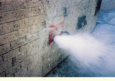
Missing female swivels or swivels out of round. They are another story. I responded to a fire in a public school in which all but one female swivel had been removed from the standpipe siamese connections along the front side of the building. The problem did not appear critical because the remaining swivel was operational. Unfortunately, the clapper valve inside this siamese connection was jammed open and could not be closed. This caused most of the supply water to flow out the other side of the connection, which could not be capped due to the missing female swivel. Although some water was available at the floor outlet, the pressure was extremely low and a hoseline had to be hand stretched from the third-due engine. While the problem of absent or severely damaged female swivels can be overcome in some cases by attaching the supply hose to a lower-floor outlet, anticipate delays in getting the standpipe system charged. Using lower-floor outlets for supply may require stretching three or more lengths of hose.
Malfunctioning one-way check valve between the siamese connection and the standpipe riser. This problem also requires that floor outlets be used for supply. Pump operators must constantly monitor their pumps for signs of churning (an indication that no water is flowing) and radio reports from the nozzle team or incident commander to ensure supply operations are successful.
Logistics
Transporting the hose, nozzle, adapters, fittings, and other tools necessary to properly hook up to a floor outlet and place a hand-line in service is the second critical task required of engine companies. In inner-city areas, elevators in apartment buildings are unreliable and often out of service completely, necessitating that hose and other equipment be lugged up the stairs--sometimes more than 20 stories. Even in residential and commercial high-rises with well-maintained elevators, water entering elevator shafts due to operating sprinklers may render them inoperable, thereby forcing fire companies to make an arduous climb.
Engine companies typically can use one of the following methods to transport their hose and equipment:
Have each firefighter carry a folded length of 2 1/2-inch hose over his shoulder and bring a separate “standpipe kit” (usually a tool bag or an old mailbag) that he can carry or sling over the opposite shoulder. This method is used by the City of New York (NY) Fire Department. In some companies, the standpipe kit is assigned to a firefighter, but many engine company officers carry it because each firefighter is already saddled with some 100-plus pounds of gear and equipment. FDNY engine companies are staffed with an officer and four or five firefighters; this affords the luxury of bringing at least three lengths of hose into the building simply by requiring each firefighter to carry one. Except for the largest cities, most engine companies respond with a total of three personnel (officer, chauffeur, and firefighter), and carrying the hose in this fashion usually is not a viable option.
Carry the hose in a soft-sided bag or strapped together with nylon seat belts or webbing. The carry bags and straps may be homemade, but several different types are available from commercial vendors. Nozzles most often are preconnected and a set amount of hose--usually 100 feet--is carried in each bag or belted load. Hose loads arranged in this fashion may be slung over the shoulder or SCBA cylinder or may be carried by two firefighters using the handles provided. Additional tools and equipment usually are carried in a separate, smaller bag.
Use a hand truck. As much as 200 feet of hose--as well as fittings and adapters needed at the hose outlet--may be carried on a single hand truck. Hand trucks are efficient because even where engine companies are minimally staffed, two people can bring to the point of operation the hose needed for the first attack line. This saves valuable time over a piecemeal delivery system and allows the first handline to be placed in service much more quickly. One drawback to hand trucks is the difficulty in pulling them up several flights of stairs. It is important that the hand truck be as lightweight as possible (without sacrificing durability) and have pneumatic tires that roll more easily over stairs.
The Standpipe Kit
What fittings, adapters, and other equipment are needed at the hose outlet to place a handline in service? The first piece of equipment required in any standpipe kit is a nozzle. Even if a nozzle already is attached to the hose, a spare nozzle may be needed if the first one breaks or becomes clogged with debris. All standpipe kits should also contain spare control wheels for the outlet valve (they often are missing) and a pipe wrench in case the valve stem is stripped and a control wheel cannot be attached. Channel-lock or vise-grip pliers often can be used instead of a pipe wrench. In FDNY, a 2 1/2-inch ¥ 2 1/2-inch in-line pressure gauge is carried in the standpipe kit and is invaluable for setting accurate nozzle pressures (see sidebar “The In-Line Pressure Gauge” on page 41 for a more complete discussion on its proper use).
The standpipe kit also should include at least two spanner wrenches, door chocks, latch straps, and a wire brush for cleaning threads. Adapters may be required in case outlet threads are incompatible with local fire department threads. In many cases, outlet threads are pipe thread and not National Standard. In areas with rampant vandalism, a universal thread adapter might be a useful addition to the kit and can be employed when threads are badly damaged. If you find that threads sometimes are missing, carry a section of pipe with pipe thread on one end and National Standard (or local fire department) thread on the other. It can be quickly attached and can save valuable time over moving down a floor to hook up.
No matter how the hose and equipment are transported from the pumper to the hose outlet, any time elevators are used a set of forcible entry tools (flathead axe and halligan) must be brought along. Engine companies should not depend on ladder or rescue companies to always be nearby and available to help should they get stuck in an elevator. In addition, it may be necessary to force a door out of (or into) a stair enclosure or force a door or breach a wall to gain access to an area of refuge.
Operating from Standpipe Systems
The final critical (and often punishing) engine company task is to place a handline in service to control and extinguish the fire. Placing this handline in service, however, requires careful consideration of several important factors: the location of the fire within the building (what floor is it on? What area or occupancy is it in?), the distance between the fire and the nearest hose outlet, limitations on developing effective fire streams due to constraints of the standpipe system, the availability of adequate numbers of firefighters to place the first handline in service promptly, and sufficient relief personnel to ensure the first handline continues an unhindered advance on the fire despite depleted air cylinders or injuries to the nozzle team. The importance of the first handline cannot be overstated, and the incident commander must direct whatever resources are necessary to support its crucial position. Remember this old firefighter adage: The fire goes as the first line goes.
Once the location of the fire has been determined (often a difficult task in itself), the appropriate hose outlet can be selected. The goal is to use one in the stairway closest to the fire to minimize the length of the stretch. One consideration in stairway selection that played a critical role at the July 1990 fire in the Empire State Building is that fire towers (also called “smokeproof towers”) created dangerous conditions for advancing nozzle teams. Fire towers most often are found in older (first- and second-generation) high-rise buildings and are designed to provide a natural draft, relieving the stairway of heat and smoke, thereby permitting occupant escape. This draft, however, will also draw fire toward the stairway once the doors are chocked open to permit a handline attack. Using another stairway, even if more remote from the fire, provides a much safer approach. (See “Fire in the Empire State Building,” by Bruce Hassett, Fire Engineering, November 1990.)
Some departments require that all standpipe hookups be made on the floor below the fire. A hookup may be permitted on the fire floor in buildings of fire-resistive construction provided the stairway doors are closed and intact. The first officer to reach the fire floor should report information on the position and condition of stairway doors. If it appears that smoke and heat will cause problems at the stair landing on the fire floor, hook up on the floor below. An important point to bear in mind is that if additional hoselines are needed, they of necessity will be attached to hose outlets one, two, and even three floors below the fire or to hose outlets in more distant stairways. Engine companies responsible for the second and third lines should anticipate this fact and bring sufficient extra hose with them. Under no circumstances should a hookup be made to a hose outlet that does not afford the nozzle team protection from heat and smoke, such as in a corridor or hallway.
After the hookup point is chosen, four important operations must be performed at the hose outlet valve before the hose can be attached:
To avoid injury, always make sure the hose outlet valve is closed before attempting to remove the outlet cap. In the case of nonautomatic dry standpipe systems, hose outlet valves may be left in the open position due to vandals, and firefighters will have to be assigned to shut these valves so as not to rob valuable pressure from the handline(s).
Remove or adjust the pressure-regulating device if present. PRDs routinely are installed on standpipe outlets to reduce, restrict, or otherwise control pressures. It is possible to find PRDs in buildings that are only six or eight stories in height and, therefore, they should not be considered strictly a problem for “big-city” fire departments. Some types of PRDs can be removed, but others are permanently affixed and cannot be removed--at least not in any reasonable amount of time. Nonremovable PRDs must be adjusted to the fully open position. The method by which this is accomplished varies by manufacturer. It is important to recognize that special tools and training may be required to adjust these devices. A third type of PRD exists, and it is the most dangerous. It cannot be removed and is not field-adjustable. It is factory set for a specific pressure; and if that pressure happens to be 55 psi, that`s all you`ll get at the outlet no matter how many pumpers are augmenting the system. The presence of permanently affixed, nonadjustable PRDs should be noted during prefire planning inspections, and this information must be disseminated to all affected fire companies.
Flush the system to remove debris that could clog or damage the nozzle. The standpipe system must be flushed thoroughly through the open hose outlet valve. Since NFPA 14 gives no requirements for installing screens or strainers within standpipe systems, garbage and debris often accumulate in the riser and piping and must be flushed so the nozzle does not clog and disrupt the critical mission of the first handline. Flushing the system in this manner also provides the nozzle team with assurance that the outlet valve is properly functional and will allow for pressure adjustments as required.
Attach the in-line gauge to better control nozzle pressure. Once the system has been flushed, the in-line gauge can be attached and the hose hooked up, ready to be charged on orders from the engine company officer. Pressure adjustments then are made by monitoring the in-line gauge and turning the control wheel at the outlet.
A question often arises as to when the handline should be charged. Some departments require that the line always be charged within the confines of the stairway, but this is not always necessary. A more practical approach is to await reports by ladder company personnel performing forcible entry and search operations, since they usually reach the fire floor first and can size up fire conditions--particularly smoke and heat levels--in the hallway. A bedroom or kitchen fire in a high-rise residential building certainly allows the nozzle team to stretch the line dry to the apartment door. In those situations when the fire is more developed (especially if wind is a factor) and the apartment door is open and cannot be closed, charging the line in the stairway may be the only safe option. Well-developed fires in commercial high-rises with open-plan floors wrapping around a center core almost always require that the fire attack be initiated from the safety of the stair enclosure. If any doubt exists, charge the line in the stairway.
Selecting Hose and Nozzle
In “Return of the Solid Stream” (Fire Engineering, September 1995), I indicated some of the reasons 2 1/2-inch hose and solid-stream nozzles must be used for standpipe firefighting. I will continue this discussion here and provide several real-world examples that serve to reinforce my rather strong opinions on this subject. Unlike firefighting operations in smaller buildings where hose can be hand stretched from engine apparatus to the fire, firefighting efforts involving the use of standpipe systems often are severely limited due to many variables outside fire department control. Standpipe systems may be poorly maintained, vandalized, improperly designed, incorrectly installed, or simply very old. As a means of balancing the many variables that exist in the standpipe firefighting equation against the need for prompt fire control and firefighter safety, the use of 2 1/2-inch hose and solid-stream nozzles is essential.
The single most important reason 2 1/2-inch hose and solid-stream nozzles with 118- or 114-inch tips should be used is that, unlike smaller-diameter hoselines and combination nozzles, they are less “pressure sensitive” at the high flows needed to safely handle rapidly developing fires in high-rise and large-area buildings. Critics say that high-volume flows can be achieved using 134- and two-inch hose, provided the proper nozzle is used and adequate pressures are available. Unfortunately, hose outlet pressures may be very limited due to the design of the standpipe system (remember, NFPA 14 states that only 100 psi need be provided at the most remote floor outlet, and only 65 psi may be available from some older systems); the presence of PRDs that cannot be removed or adjusted to the fully open position; vandalism; and maintenance deficiencies.
Medium-diameter (134- and two-inch) handlines “eat up” available pressure due to their excessive friction loss per length at high flows. Whereas at a flow of 250 gpm, the friction loss per length of 2 1/2-inch hose is only about six psi; it jumps to 25 psi per length of two-inch hose and a whopping 48 psi per length of 134-inch hose. If a combination nozzle is used (requiring 100 psi) and three lengths of hose are needed to reach the fire, the outlet pressure using two-inch hose must be 175 psi and with 134-inch hose; 244 psi is required. Not only are pressures this high unsafe, they often are impossible to attain. A friend was operating the pumps at a standpipe operation with a pump discharge pressure higher than 200 psi. This pressure was needed to supply 134-inch hose and a combination (fog) nozzle. All of a sudden, he noticed that he was standing in a pool of water. Investigation showed the underground pipe between the freestanding siamese connection and the building had failed, compromising the entire firefighting operation. Failures of this type are more common than many firefighters think, and high pressures are partially to blame.
Even if a 118-inch solid-stream tip operated at 40 psi is used with a medium-diameter handline, required outlet pressures are still 106 psi for three lengths of two-inch hose and 169 psi for 134-inch at a flow of approximately 236 gpm. A three-length stretch of 2 1/2-inch hose coupled with a 118-inch solid-stream tip operated at 40 psi will flow 236 gpm with a required outlet pressure of only 58 psi. A 114-inch tip at 40 psi will flow 293 gpm. In a test I conducted on various types of nozzles, a 118-inch tip supplied with only 20 psi at the base of the nozzle inlet produced a 203 gpm stream with an effective reach estimated at 80 feet. At 40-psi base inlet pressure, the flow increased to 298 gpm; and the effective stream reach was well over 100 feet. For test purposes, the nozzles were attached to a ground-based monitor set at a 65-degree angle--not a hand-line. This no doubt increased the flow due to reduced water turbulence at the nozzle inlet because of the vanes in the monitor playpipe. Even assuming the flow results were, say, 15 to 20 percent higher than could be expected from a handline under fireground conditions, no other hose and nozzle combination will provide the low pressure performance and high margin of safety as a solid-stream tip attached to 2 1/2-inch hose.
Another criticism of 2 1/2-inch hose concerns the fact that it is a labor-intensive hand-line and most departments do not have the staffing levels to use it. This argument is severely flawed for a number of reasons. First, it has been my observation that departments that have abandoned 2 1/2-inch line often are the same ones carrying three-inch hose and state that if really big flows are needed, the three-inch can be pressed into service. Three-inch-diameter hose is not a handline--it is a supply line. If staffing isn`t available to handle 2 1/2-inch hose, how can the heavier, stiffer, less maneuverable three-inch line be safely and effectively employed?
Second, many of the problems in handling 2 1/2-inch hose can be overcome simply by training engine company personnel in its proper use. Unlike 2 1/2-inch hose of years past with its heavy double jackets and solid brass couplings, newer types of hose are lighter and easier to carry and deploy. If solid-stream nozzles are used, reaction forces can be minimized while providing unparalleled stream reach and volume of flow. In addition, newer solid-stream nozzles are lightweight, compact, and much less unwieldy than older types. The most effective method of using 2 1/2-inch is for the nozzleman to maintain enough hose out in front so that he has an arm`s length reach to the bale of the shutoff. The backup man then pins the hose to the floor using his hands and leans into the nozzleman`s SCBA cylinder. This provides the nozzleman with adequate stream mobility while easing the reaction force burden. If the line must be moved, gate down, pick up the line, and move forward. Pistol grips may also help the nozzleman maintain effective line control.
Third and last, many departments believe medium-diameter attack lines that can be handled by two firefighters have enough “punch” to handle fires in tall buildings with large floor areas. Let me dispel this belief with some facts about fires in high-rise residential and office buildings. Although most fires in high-rise buildings are of a relatively minor nature, occasionally one occurs that sorely challenges the tactical resources of even the largest fire departments.
A fire on the 18th floor of a high-rise apartment building in the Bronx during November 1994 required the services of three 2 1/2-inch lines operating together, each flowing 250 gpm, to move out of the stairway and suppress the fire, which involved two entire apartments. This firefighting effort was hampered by high winds. On windy days, fires can reach blowtorch proportions on upper floors, especially in residential buildings with narrow, concrete hallways that act like giant nozzles, accelerating the advancing flame front at great and deadly speed. Even on relatively calm days, wind conditions on the upper floors are often dramatically different from those at street level. Some high-rise apartment buildings contain duplex and triplex apartments, and a fire in the Bronx several years ago involving the “down” portion of a duplex apartment on the sixth floor was finally extinguished only by stretching a third handline over an aerial ladder through the fire-apartment window. The two interior lines were beaten back by high heat levels and numerous logistical problems. Fires in the lower-floor areas of duplex and triplex apartments are akin to fighting a cellar fire in the sky.
When discussing fires in high-rise commercial buildings, especially wind-driven fires, personnel needs may exceed severalfold those for residential building fires. Deputy Chief James Murtagh of FDNY, a nationally recognized authority on high-rise firefighting strategy and tactics, has dubbed a well-developed fire in a commercial high-rise building the “100-man fire.” If your department or mutual-aid network cannot bring at least 100 firefighters to the scene early on, the fire may not be successfully controlled. Consider that it will require up to three engine companies to place a single handline in service (marrying together three or four engine companies when staffing levels are light is a very wise idea), an additional three engine companies for relief purposes, and perhaps two or three more if the firefighting efforts are drawn out and firefighters begin to fall from heat exhaustion, burn injuries, and depleted air cylinders. Remaining personnel will be used to place additional handlines in service and perform forcible entry, search, ventilation, and other tasks. Certainly, if 100 firefighters and officers are needed to successfully handle a serious fire in a commercial high-rise building, complaints about a lack of personnel to use 2 1/2-inch hose quickly lose credibility.
There is one more area in which solid-stream nozzles provide the nozzle team with an increased level of operational safety--they don`t clog very easily. Can a solid-stream nozzle clog? Absolutely, and my engine company in the Bronx clogged two within several months of each other during standpipe operations. In both cases, rubber handballs lodged within the standpipe system piping were the culprits. Aluminum cans and certain other items also can clog a solid-stream tip. That is why it is so important to flush the system at the outlet before connecting the hose. Even after flushing, there is always the possibility that some entrapped debris may work its way through the riser and hose to the nozzle. Depending on the circumstances, a small rock or other hard object propelled along at high velocity in the water stream could clog or damage the internal workings of a fog nozzle, while the same object will pass through a solid-stream tip.
Other objects can also clog fog nozzles and render them completely useless. The following story was related to me by a fire instructor friend of mine. While he was conducting a basic firefighter training class, students stretched a 134-inch safety line with an automatic fog nozzle off the dry standpipe in the training building. They charged the line and bled off the trapped air. Some time later, while they attempted to wet down bales of hay with this line, the automatic fog nozzle shut down completely. Later, a second, similar nozzle also shut down suddenly. Fortunately, these lines were not being used to practice extinguishing room fires. The nozzles were removed from the hose. In both cases, the tail and hindquarters of a mouse were found at the nozzle inlet. Apparently, a family of mice had taken up residence in the standpipe riser, and the mechanisms of both nozzles became clogged with mouse entrails. As my friend pointed out to the amazed students, a clogged nozzle is extremely dangerous in an actual fire situation. By using an open-bore tip, the poor mouse would have been hydraulically launched toward the fire in the stream, but the safety of the nozzle team would never have been in doubt.
Safe and efficient operations using standpipe systems require that engine company personnel plan for a host of contingencies. I know of very few standpipe “jobs” that weren`t fraught with difficulties due to the severity of the fire, the condition of the standpipe system, or both. Well-trained and disciplined engine companies not only are prepared for the routine but are able to overcome obstacles to get the job done, even in the face of extreme adversity. n
Thanks to the following individuals for their invaluable assistance in preparing this article: Professor Glenn P. Corbett, P.E., John Jay College of Criminal Justice and Fire Engineering technical editor, and Diana Robinson, senior librarian at the New York State Academy of Fire Science. Thanks also to the officers and members of FDNY Engine Company 48 and the following additional FDNY units: Engine Company 38 in the Bronx and Engine Company 34 in Manhattan.
This article is dedicated to the memory of Firefighter John Askin, Engine Company 48, who passed away a little over a year ago and who taught me and so many others what it means to be an “Engineman.”
Suggested Reading
Chapman, Elmer F. “More on High-Rise Tactics: Standpipe Operations.” Fire Engineering. Jan. 1989, pp. 47-49.
Chapman, Elmer F. “Guidelines for Strategic Decision Making at High-Rise Fires.” Fire Engineering. Sept. 1995, pp. 66-70.
Corbett, Glenn P. “Standpipe Systems.” Fire Engineering. Mar. 1993, pp. 36-43.
Fire Chief`s Handbook, The (Fifth Edition), Chapter 26: “Fire Protection Systems,” Glenn P. Corbett. (Saddle Brook, NJ: Fire Engineering Books and Videos, 1995.)
Fire Protection Handbook (17th Edition), Section 18, Chapter 6: “Standpipe and Hose Systems,” Robert M. Hodnett. (Quincy, MA: National Fire Protection Association.)
Fornell, David P. “Standpipe Operations.” Fire Engineering. Aug. 1991, pp. 71-84.
Fredericks, Andrew A. “Return of the Solid Stream.” Fire Engineering. Sept. 1995, pp. 44-56.
Hassett, Bruce. “Fire in the Empire State Building.” Fire Engineering. Nov. 1990, pp. 51-63.
NFPA 14, Standard for the Installation of Standpipe and Hose Systems. (Quincy, MA: National Fire Protection Association, 1993.)
Illustrations
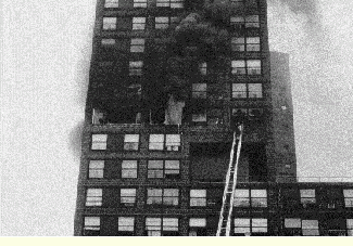
Fires in buildings equipped with standpipe systems present many challenges. This fire on the 10th floor of a high-rise apartment house in Bronx, New York, required two 212-inch handlines and the efforts of more than 75 firefighters to bring it under control. One handline was advanced through a breached opening in the partition wall between the fire apartment and an adjoining one.
This siamese connection is clogged with garbage and debris – a common problem in inner-city areas. Never stick your fingers or any part of your hand into a siamese connection. Besides possible cuts from broken glass, you might find hypodermic needles inside that drug users have hidden or discarded.
This standpipe siamese connection contains only one working female swivel. In addition, the clapper valve is jammed open, allowing water to flow back out the open side. Vandalized siamese connections often necessitate the use of lower-floor hose outlets for supply operations.
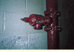
Hose outlets often are vandalized and have caps and control wheels missing. Standpipe kits must be equipped with spare control wheels and a pipe wrench or channel lock pliers in the event the valve stem is stripped and a spare control wheel cannot be used. Standpipe systems must be flushed thoroughly at the hose outlet before a handline is attached. Debris lodged within the riser or piping can clog or damage a nozzle and jeopardize the entire fire attack operation.
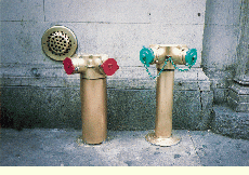
The siamese connection on the right is fitted with “regular” caps; the siamese connection on the left is fitted with “break-away” vandalproof caps. The City of New York building code requires that siamese connections (or at least the caps) be color coded for ease of identification. Red indicates a standpipe siamese; green, automatic sprinkler systems; yellow, combination sprinkler/standpipes; and aluminum (or silver), nonautomatic dry sprinkler systems (often found in cellars and subcellars of older commercial buildings).
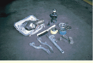
This is FDNY Engine Company 48`s standpipe kit. It contains the following items: 212-inch controlling nozzle with 118-inch tip and 12-inch outer stream or overhaul tip; in-line pressure gauge; two spanner wrenches; spare control wheels; pipe wrench; wire brush; door chocks; color-coded adapters (blue indicates pipe thread to FDNY thread and yellow indicates National Standard thread to FDNY thread); and a section of pipe threaded on each end, for use if outlet threads are missing altogether.
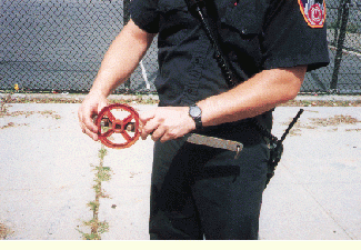
This firefighter is demonstrating the use of a homemade wrench designed to be inserted between the spokes of the control wheel, allowing the outlet valve to be opened much more easily.
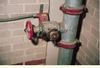
Pressure-reducing valves must be identified by type during preplanning, including notations regarding their field-adjustability. This valve, for example, requires the use of a special tool to adjust the discharge pressure if this pressure was incorrectly set during inspection/maintenance. Other pressure-reducing valves are not field-adjustable. Obviously, you must have this information before the fire.
Fire Department High-pressure Pumpers
To supply required handline pressures to standpipe outlets on the upper floors of the tallest “skyscrapers,” the City of New York (NY) Fire Department has in service seven “high-pressure” pumpers. Each high-pressure pumper is capable of supplying 500 gpm at a pump discharge pressure (PDP) of 700 psi utilizing a third-pump stage. If building fire pumps should completely fail, at least one and perhaps two 212-inch handlines with 118-inch nozzle tips can be placed in service on the 110th floor of either World Trade Center tower (a required PDP of some 650 psi).
Due to the inherent dangers involved in employing pressures so high, FDNY has developed specific procedures to be followed once the incident commander orders the use of high-pressure pumping operations. Section 5 of FDNY`s Firefighting Procedures, Volume 1, Book 5, “High-Rise Office Buildings” lists the following steps to be taken prior to activation of the third pump stage:
The operation must be supervised by a battalion chief.
Two engine company chauffeurs must be assigned to the high-pressure pumper--one to operate the pumps and the second to monitor the handheld radio and provide a communications link to the officer in charge due to the high noise levels.
Only special three-inch, high-pressure hose must be used. All high-pressure hose couplings and other necessary fittings are painted white for identification. They are also noticeably heavier than standard couplings and fittings.
The high-pressure hose must be attached to a dedicated discharge gate located at the rear or on the side of the pumper opposite the pump control panel.
The high-pressure hose must be tethered to a “substantial” object to prevent violent whipping should it fail.
All personnel must remain at least 50 feet from the high-pressure hose, and this area should be cordoned off with rope or barrier tape.
Despite NFPA 14 requirements for the use of “extra-heavy pattern” fittings on standpipe systems in buildings where pressures will exceed 175 psi, the potential for piping or riser failure is so great that an additional FDNY policy requires that all civilian and fire department personnel evacuate the stairway containing the high-pressure riser. Firefighters are not to enter this stairway unless absolutely necessary and are to exit as quickly as possible. The violent failure of a riser subjected to a pressure of several hundred pounds per square inch would no doubt be lethal to anyone nearby.
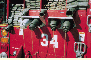
The discharge elbow painted white is a “high-pressure” type to be used in conjunction with three-inch hose designed to withstand pump discharge pressures upward of 700 psi. Only the OIC of a high-rise fire can order the use of high-pressure pumping operations. In addition to midtown Manhattan`s 34 Engine pictured here, the following FDNY engine companies are assigned high-pressure pumpers: 6, 10, and 26 in lower Manhattan; 54 and 65, midtown; and 258, Long Island City, Queens. Three high-pressure pumpers are available as spares.
The In-line Pressure Gauge
The in-line pressure gauge is a simple piece of equipment that can enhance the efficiency of standpipe operations. The gauge is connected to the hose outlet from which a handline is stretched and allows the firefighter assigned at the outlet to read the pressure being supplied to the line and make adjustments, as required. The firefighter stationed at the outlet is equipped with a portable radio to monitor the progress of the nozzle team and to charge and shut down the line on orders of the engine company officer. Final pressure adjustments are made after water begins flowing and not under static conditions.
Development of adequate fire streams using standpipe systems begins with the engine company chauffeur (or pump operator). In the City of New York (NY) Fire Department, chauffeurs are required to supply 100 psi to the siamese connection plus an additional five psi per floor above grade. The 100 psi takes into account the following:
- friction loss in two lengths (100 feet) of 312-inch hose used to supply the siamese connection;
- friction losses due to the siamese connection itself, as well as the system riser, piping, and fittings;
- friction loss in three lengths (150 feet) of 212-inch handline; and
- nozzle pressure of 40 psi for a 118-inch solid-stream tip.
If more lengths of either 312-inch or 212-inch hose are required, the pump operator must adjust the pump discharge pressure accordingly.
If an in-line gauge is not used, the hose outlet is opened without knowledge as to the pressure being delivered to the nozzle. If the system pressure is excessive, injuries and/or a burst length is possible. If insufficient pressure is being supplied, the flow from the nozzle may be inadequate. By using the in-line gauge to adjust nozzle pressure, the entire operation becomes safer and assures a more effective stream.
The specific pressure required at the outlet is based on the number of hose lengths used and the diameter. The gauge used by Engine Company 48 in the Bronx is labeled with preset pressures for typical hose stretches:
- 70 psi for three lengths of 212-inch hose;
- 80 psi for four lengths of 212-inch hose; and
- 90 psi for three lengths of 212-inch hose and one length of 134-inch hose.
These pressures were determined through flow tests of actual hose layouts and include a 40-psi nozzle pressure using a 118-inch tip and a friction loss of about 10 psi per length of 212-inch hose. While FDNY procedures require the use of 212-inch hose for all standpipe operations, in certain situations--such as for minor fires in residential occupancies and for overhaul--the use of a lead length of 134-inch hose equipped with a 118-inch tip may permit the nozzle team greater mobility without a severe flow reduction. If outlet pressures do not permit its use, the entire stretch is made up of 212-inch hose.
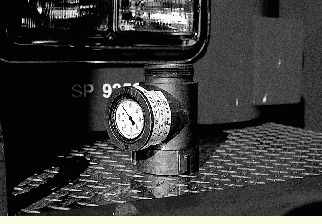
Engine Company 48`s in-line pressure gauge is marked with preset pressures for three different hose layouts. The pressure settings are also notched out on the face of the gauge and painted with fluorescent orange paint. Adjusting pressure at the hose outlet increases nozzle pressure accuracy and provides a more effective fire stream.
Authors
JOHN P. GRASSO is a firefighter with the City of New York (NY) Fire Department, assigned to Engine Company 48 in the Bronx. He has bachelor`s degrees in mechanical engineering and fire science and a master`s degree in fire protection management from John Jay College of Criminal Justice. He is an instructor at the Rockland County Fire Training Center in Pomona, New York, and an adjunct instructor in the New York City Health and Hospital Corporation`s Hospital Police entry level and in-service training programs at John Jay College.
ANDREW A. FREDERICKS is a 16-year veteran of the fire service and a firefighter with the City of New York (NY) Fire Department, assigned to Engine Company 48 in the Bronx. He is a New York State-certified fire instructor at the Rockland County Fire Training Center in Pomona, New York, and an adjunct instructor at the New York State Academy of Fire Science. He has two bachelor`s degrees, one in political science and the other in public safety, with a specialization in fire science, and a master`s degree in fire protection management from John Jay College of Criminal Justice.
 Last edited 2015-11-04 21:59 UTC by
 ![[Twitter]](/img/twitter_box.png)
![[RSS]](/img/rss_box.png)